- FT-ICR Mass Spectrometer Electronic Systems Rebuild
- Sensor Integration Block
- Low-Noise Universal Power Supply
- High-Current Digitally Controlled Pulser
- Open-Circuit Voltage Decay System
- High Current Device Characterizer
- Narrow-Pulse Test Bed for Wide Bandgap Devices
- Extracting Electrical Energy from Rotational Devices
Fourier Transform Ion Cyclotron Resonance (FT-ICR) Mass Spectrometer Electronic Systems Rebuild
The Center for Emerging Energy Sciences (CEES), having previously acquired a number of Fourier Transform Ion Cyclotron Resonance (FT-ICR) mass spectrometers called Quantras that were manufactured by Siemens Applied Automation in the late ’90s, has undertaken the effort to completely rebuild the electronic systems of these units and generate a custom software suite to control parameters and acquire data via a Graphical User Interface (GUI).
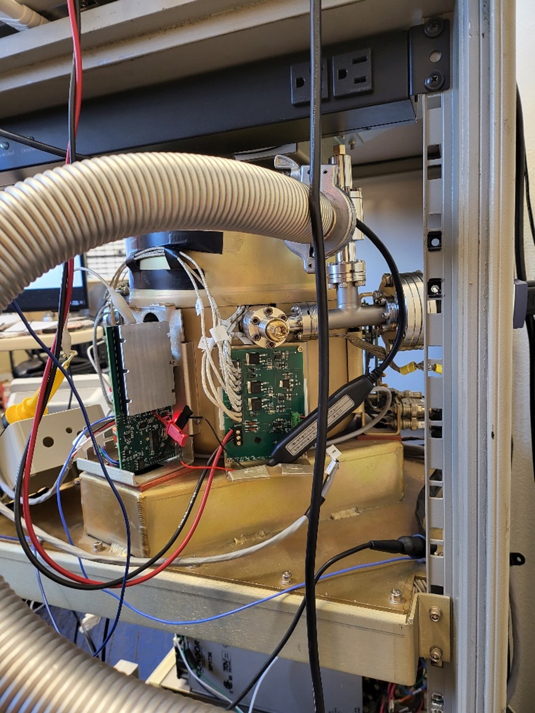
These units were designed to be controlled by an integrated half-board computer running the Linux operating system. As these Quantra units are roughly twenty-plus years old, the majority of them are experiencing assorted hardware, firmware, and software failures. As the hardware designs and the Linux-based software are proprietary, and Siemens is unwilling to share either code or schematics, they are in effect ‘black-boxes,’ and the CEES staff are forced to create work-arounds to restore functionality as needed as issues invariably arise.
The goal of this project is to create modern hardware systems to replace the legacy electronic systems in the Quantra. These new replacement systems have been completely designed by CEES engineers in-house, thus ensuring comprehensive documentation of hardware, firmware, and the requisite Windows-based control and data acquisition GUI software. The design philosophy behind the new Quantra unit is multi-faceted:
- The new instrument has been designed as a USB computer peripheral instrument.
- The electronics of the unit follows a completely modular design philosophy where each subsystem is ‘intelligent’ and wholly self-contained.
- Each subsystem communicates with a main unit, which in turn is controlled from the PC-based GUI via a USB port.
- During normal operation, a user sets parameters through the GUI, the main unit then directs the addressed module to adjust that parameter, reads the value, and checks for non-fatal errors.
- Each module also monitors itself in real-time for any fatal hardware or firmware errors, and reports these to the main unit via an interrupt mechanism on the I2C bus used for module to module communication.
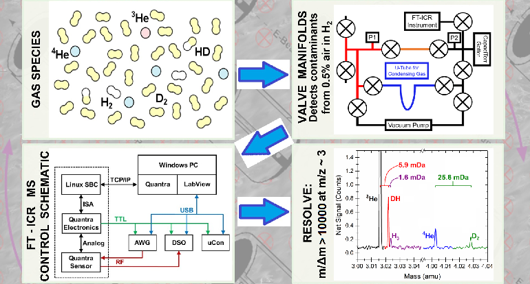
In addition to creating a highly maintainable FT-ICR unit, the new hardware allows any subsystem to be redesigned or replaced at will. As the new unit consists of ‘smart’ modules that digitize measured parameters physically close to sensors and generate and buffer control signals similarly close to where they are applied, these systems emit less, and are far less susceptible to, electrical noise. The raw power supplies for the new electronic systems are linear as well, as opposed to the original switch-mode supplies that generated EMI which coupled into several key systems. In addition, as each system is now under the control of a dedicated processor, subsystems such as the units' heaters can now be disabled during the sensitive measurement process, and then reenabled afterwards. Each hardware function is autonomous, and directed by a main module. A custom software suite is used to control settings and read data. Figure 1 shows a block diagram of the new FT-ICR electronic systems:

The majority of the modules currently utilize the Inter-Integrated Circuit (I2C) bus for communications with the main module. Provisions have also been added for SPI, CAN and UART busses if so desired at a later time. Except for high-level (catastrophic) errors in a module, e.g., a power brown-out, the main module is the sole bus master and drives all data exchange and control settings. Figure 2 is a simplified firmware flow chart of the main module and one sub-module:

As an example of a smart module, figure 3 displays a block diagram and a photograph (bottom right) of the module that generates the FT-ICR trap plate potentials, reads the nanoamp level currents of any impinging electron beams on the trap plates (an undesired result which requires adjustment of the electron beam to correct), and reads and controls the temperature of the Quantra's oven, valve, and gas inlet. Also pictured (top left photo) is the submodule that switches power to the heating elements, and monitors the bimetallic thermal circuit breakers as well as the heater supply voltages.


Physical System

The FT-ICR rebuild is nearly complete with one submodule remaining, and all systems have shown an improvement over the original electronics by nearly every metric.
Sensor Integration Block
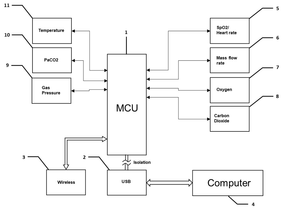
The Sensor Integration Block (SIB) may be inserted in-line between a respiratory mask and any commercially available CPAP, respirator or breathing device. A portable version has also been produced for field deployment. This SIB records, logs, and analyzes a comprehensive dataset, and displays this data on custom Windows-based software.
Block Diagrams


Physical System

Low-Noise Universal Power Supply
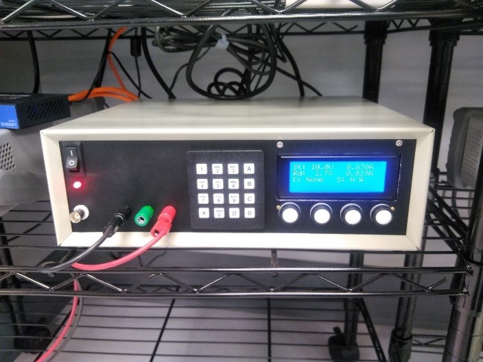
This system is a custom constant-voltage, constant-current, very low-noise, digitally controllable power supply with a built-in function generator and the ability for external modulation of current or voltage. Custom software was also written for PC control of the unit.
Block Diagram

Physical System


High-Current Digitally Controlled Pulser for High Magnetic Field Applications
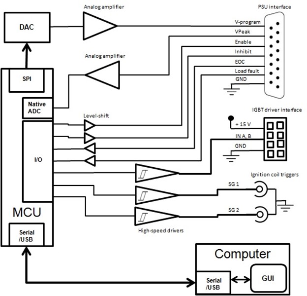
The high-current pulser system drives a specially designed coil to achieve fast, controllable magnitude and pulse-width magnetic fields in the 0 to 5 Tesla range.
Block Diagram

Physical System

Open-Circuit Voltage Decay System
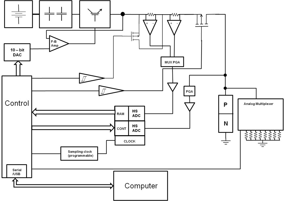
This system performs open circuit voltage decay analysis on packaged PN junction devices for use with injection-dependent lifetime spectroscopy techniques. The system injects currents that can range from ~1 mA to 100 A in a pulsed manner through an electronically controlled, fast, nearly ideal switch to disconnect the device being analyzed. Data is acquired and uploaded to a custom program that automates much of the analysis required for carrier lifetime spectroscopy.
Block Diagram

Physical System

High Current Device Characterizer
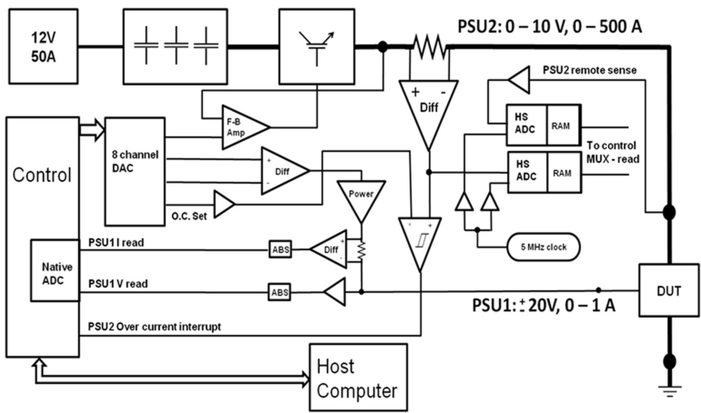
This high current characterization system is comprised of two independently controlled power supply units: PSU1 and PSU2. PSU1, a ±20 V at 1 A supply is intended principally for powering the control lead of a three terminal device, or it can be used for relatively low current tracing (≤ 1 A). This supply can be operated in either a pulsed or a continuous manner. PSU2 is a 10 V @ 500 A max supply that operates only in a pulsed mode. The output of PSU2 is produced by a high power linear amplifier with feedback that utilizes paralleled Insulated Gate Bipolar Junction Transistors (IGBTs) as series-pass elements. The unit derives IV characteristics for very high-current devices.
Block Diagram

Physical System

Narrow-Pulse Test Bed for Evaluation of Experimental Wide Bandgap Semiconductor Devices
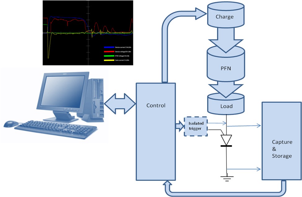
This system performs automated high-energy repetitive stress-cycling of experimental semiconductor devices, recording all pertinent waveforms with built-in, high frequency data acquisition and alternates device characterization at chosen intervals via a built-in, high voltage, high current curve tracer, switching between the two sets of circuitries with a custom-designed 3-pole, 3-throw electromechanical switch.
Block Diagrams


Physical System

System for Extracting Electrical Energy from Inertial Energy of Rotational Devices
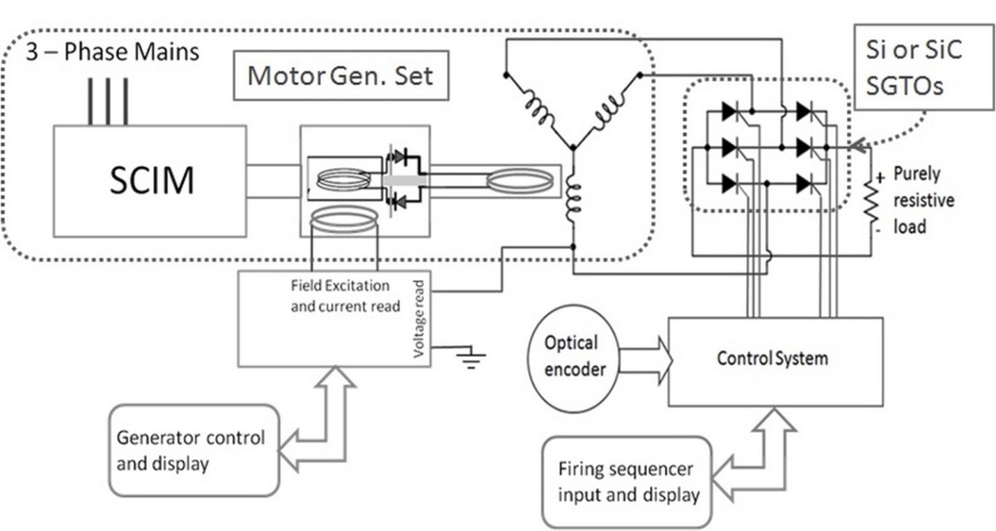
This system was designed to extract electrical energy from the mechanical inertia of rotational machines in a pulsed-power (fast) manner.
Block Diagram

Physical System

See Smart Modules for Improved Sensing, which applies the FT-ICR design philosophy to other measurement systems, and Precision Metrology & Measurement Science. Our in-house fabrication facilities are listed under capabilities.